


Home > Textbooks > Basic Electronics > Wave Shaping > Differentiators >
Wave Shaping
Differentiators
Differentiation is the direct opposite of integration. In the RC integrator, the output is taken from the capacitor. In the differentiator, the output is taken across the resistor. Likewise, this means that when the RL circuit is used as a differentiator, the differentiated output is taken across the inductor.
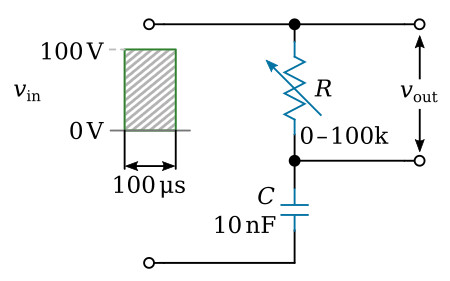
An application of Kirchhoff's law shows the relationship between the waveforms across the resistor and capacitor in a series network. Since the sum of the voltage drops in a closed loop must equal the total applied voltage, the graphical sum of the voltage waveforms in a closed loop must equal the applied waveform. The figure below shows a differentiator circuit with the output taken across a variable resistor.
Short Time-Constant Differentiator
With the variable resistor set at 1,000 ohms and the capacitor value of 0.01 microfarad, the time constant of the circuit is 10 microseconds. Since the input waveform has a duration of 100 microseconds, the circuit is a short time-constant circuit.
At the first instant of time in the short time-constant circuit, the voltage across the capacitor is 0. Current flows through the resistor and causes a maximum voltage to be developed across it. This is shown at the first instant of time in the graph of the figure below.
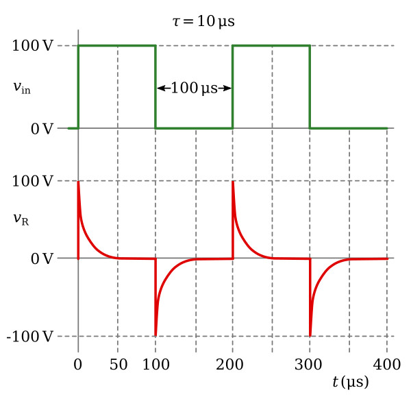
As the capacitor begins accumulating a charge, the voltage developed across the resistor will begin to decrease. At the end of the first time constant, the voltage developed across the resistor will have decreased by a value equal to 63.2 percent of the applied voltage. Since 100 volts is applied, the voltage across the resistor after 1τ will be equal to 36.8 volts. After the second time constant, the voltage across the resistor will be down to 13.5 volts. At the end of the third time constant, vR will be 5 volts and at the end of the fourth time constant, 2 volts. At the end of the fifth time constant, the voltage across the resistor will be very close to 0 volts. Since the time constant is equal to 10 microseconds, it will take a total of 50 microseconds to completely charge the capacitor and stop current flow in the circuit.
As shown in the figure above the slope of the charge curve will be very sharp. The voltage across the resistor will remain at 0 volts until the end of 100 microseconds. At that time, the applied voltage suddenly drops to 0, and the capacitor will now discharge through the resistor. At this time, the discharge current will be maximum causing a large discharge voltage to develop across the resistor. This is shown as the negative spike in the figure above. Since the current flow from the capacitor, which now acts like a source, is decreasing exponentially, the voltage across the resistor will also decrease. The resistor voltage will decrease exponentially to 0 volts in 5 time constants. All of this discharge action will take a total of 50 microseconds. The discharge curve is also shown in the figure above. At the end of 200 microseconds, the action begins again. The output waveform taken across the resistor in this short time-constant circuit is an example of differentiation. With the square wave applied, positive and negative spikes are produced in the output. These spikes approximate the rate of change of the input square wave.
Medium Time-Constant Differentiator
The output across the resistor in an RC circuit of a medium time constant is shown in the figure below. The value of the variable resistor has been increased to a value of 10,000 ohms. This means that the time constant of the circuit is equal to the duration of the input pulse or 100 microseconds. For clarity, the voltage waveforms developed across both the resistor and the capacitor are shown. As before, the sum of the voltages across the resistor and capacitor must be equal to the applied voltage of 100 volts.
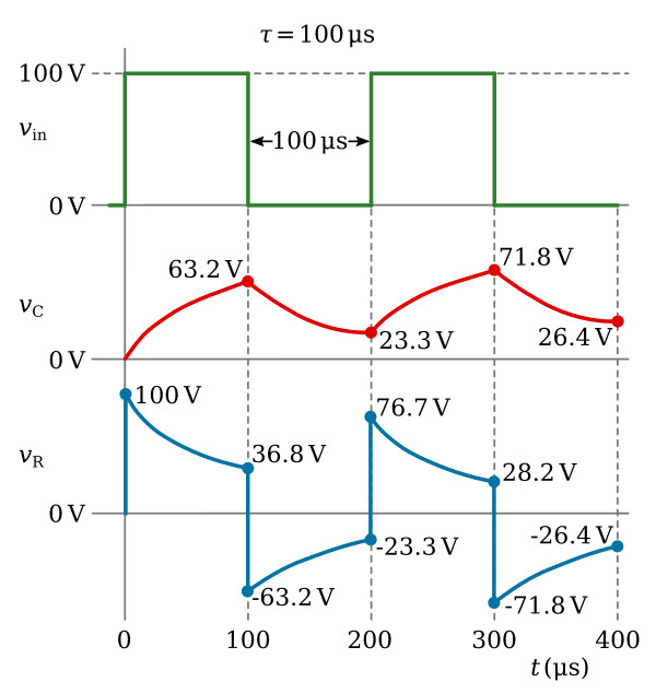
At the first instant of time, a pulse of 100 volts in amplitude with a duration of 100 microseconds is applied. Since the capacitor cannot respond quickly to the change in voltage, all of the applied voltage is felt across the resistor. The figure above shows the voltage across the resistor (vR) to be 100 volts and the voltage across the capacitor (vC) to be 0 volts. As time progresses, the capacitor charges. As the capacitor voltage increases, the resistor voltage decreases. Since the time that the capacitor is permitted to charge is 100 microseconds (equal to 1τ in this circuit), the capacitor will charge to 63.2 percent of the applied voltage at the end of 1τ, or 63.2 volts. Because Kirchhoff's law must be followed at all times, the voltage across the resistor must be equal to the difference between the applied voltage and the charge on the capacitor (100 - 63.2 volts), or 36.8 volts.
At the end of the first 100 microseconds, the input voltage suddenly drops to 0 volts. The charge on the capacitor (-63.2 volts) becomes the source and the entire voltage is developed across the resistor for the first instant.
The capacitor discharges during the next 100 microseconds. The voltage across the resistor decreases at the same rate as the capacitor voltage and total voltage is maintained at 0. This exponential decrease in resistor voltage is shown during the second 100 microseconds in the figure above. The capacitor will discharge 63.2 percent of its charge to a value of 23.3 volts at the end of the second 100 microseconds. The resistor voltage will rise in the positive direction to a value of -23.3 volts to maintain the total voltage at 0 volts.
At the end of 200 microseconds, the input voltage again rises suddenly to 100 volts. Since the capacitor cannot respond to the 100-volt increase instantaneously, the 100-volt change takes place across the resistor. The voltage across the resistor suddenly rises from -23.3 volts to +76.7 volts. The capacitor will now begin to charge for 100 microseconds. The voltage will decrease across the resistor. This charge and discharge action will continue for many cycles. Finally, the voltage across the capacitor will rise and fall by equal amounts both above and below about a 50-volt level. The resistor voltage will also rise and fall by equal amounts to about a 0-volt level.
Long Time-Constant Differentiator
If the time constant for the circuit of RC differentiator is increased to make it a long time-constant circuit, the differentiator output will appear more like the input. The time constant for the circuit can be changed by either increasing the value of capacitance or resistance. In this circuit, the time constant will be increased by increasing the value of resistance from 10,000 ohms to 100,000 ohms. Increasing the value of resistance will result in a time constant of 1,000 microseconds. The time constant is 10 times the duration of the input pulse. The output of this long time-constant circuit is shown in the figure below.
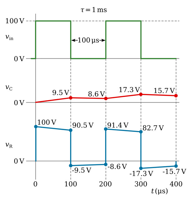
At the first instant of time, a pulse of 100-volts amplitude with a duration of 100 microseconds is applied. Since the capacitor cannot respond instantaneously to a change in voltage, all of the applied voltage is felt across the resistor. As time progresses, the capacitor will charge and the voltage across the resistor will be reduced. Since the time that the capacitor is permitted to charge is 100 microseconds, the capacitor will charge for only 1/10 of 1τ or to 9.5 percent of the applied voltage. The voltage across the resistor must be equal to the difference between the applied voltage and the charge on the capacitor (100 - 9.5 volts), or 90.5 volts.
At the end of the first 100 microseconds of input, the applied voltage suddenly drops to 0 volts, a change of 100 volts. Since the capacitor is not able to respond to so rapid a voltage change, it becomes the source of 9.5 volts. This causes a -9.5 voltage to be felt across the resistor in the first instant of time. The sum of the voltage across the two components is now 0 volts.
During the next 100 microseconds, the capacitor discharges. The total circuit voltage is maintained at 0 by the voltage across the resistor decreasing at exactly the same rate as the capacitor discharge. This exponential decrease in resistor voltage is shown during the second 100 microseconds of operation. The capacitor will now discharge 9.5 percent of its charge to a value of 8.6 volts. At the end of the second 100 microseconds, the resistor voltage will rise in a positive direction to a value of -8.6 volts to maintain the total circuit voltage at 0 volts.
At the end of 200 microseconds, the input voltage again suddenly rises to 100 volts. Since the capacitor cannot respond to the 100-volt change instantaneously, the 100-volt change takes place across the resistor. This step-by-step action will continue until the circuit stabilizes. After many cycles have passed, the capacitor voltage varies by equal amounts above and below the 50-volt level. The resistor voltage varies by equal amounts both above and below a 0-volt level.
The RC networks which have been discussed in this section may also be used as coupling networks. When an RC circuit is used as a coupling circuit, the output is taken from across the resistor. Normally, a long time-constant circuit is used. This, of course, will cause an integrated wave shape across the capacitor if the applied signal is nonsinusoidal. However, in a coupling circuit, the signal across the resistor should closely resemble the input signal and will if the time constant is sufficiently long. By referring to the diagram in the figure above, you can see that the voltage across the resistor closely resembles the input signal. Consider what would happen if a pure sine wave were applied to a long time-constant RC circuit (R is much greater than XC). A large percentage of the applied voltage would be developed across the resistor and only a small amount across the capacitor.


