


Home > Textbooks > Basic Electronics > Filters > Filter Basics >
Filters
Filter Basics
In many practical applications of complex circuits, various combinations of direct, low-frequency, audio-frequency, and radio-frequency currents may exist. It is frequently necessary to have a means for separating these component currents at any desired point. An electrical device for accomplishing this separation is called a filter.
A filter circuit consists of inductance, capacitance, and resistance used singularly or in combination, depending upon the purpose. It may be designed so that it will separate alternating current from direct current, or so that it will separate alternating current of one frequency (or a band of frequencies) from other alternating currents of different frequencies.
The use of resistance by itself in filter circuits does not provide any filtering action, because it opposes the flow of any current regardless of its frequency. What it does, when connected in series or parallel with an inductor or capacitor, is to decrease the "sharpness", or selectivity, of the filter. Hence, in some particular application, resistance might be used in conjunction with inductance or capacitance to provide filtering action over a wider band of frequencies.
Filter circuits may be divided into four general types: low-pass, high-pass, bandpass, and band-reject filters.
Electronic circuits often have currents of different frequencies. As an example, the AC signal input to an audio amplifier can have high- and low-audio frequencies; the input to an RF amplifier can have a wide range of radio frequencies.
In such applications where the current has different frequency components, it is usually necessary for the filter either to accept or reject one frequency or a group of frequencies. The electronic filter that can pass on the higher-frequency components to a load or to the next circuit is known as a high-pass filter. A low-pass filter can be used to pass on lower-frequency components.
Before discussing filters further, we will review and apply some basic principles of the frequency-response characteristics of the capacitor and the inductor. Recall the basic formula for capacitive reactance and inductive reactance:

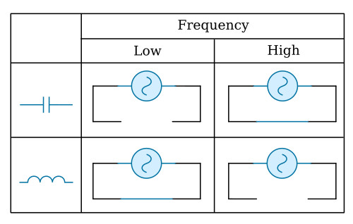
Assume any given value of L and C. If we increase the applied frequency, XC decreases and XL increases. If we increase the frequency enough, the capacitor acts as a short and the inductor acts as an open. Of course, the opposite is also true. Decreasing frequency causes XC to increase and XL to decrease. Here again, if we make a large enough change, XC acts as an open and XL acts as a short. The figure below gives a pictorial representation of these two basic components and how they respond to low and high frequencies.
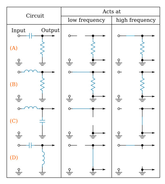
If we apply these same principles to simple circuits (voltage dividers), such as the ones in the figure below, they affect input signals as shown. For example, in view (A) of the figure, a low frequency is blocked by the capacitor which acts as an open and at a high frequency the capacitor acts as a short. By studying the figure, it is easy to see how the various components will react in different configurations with a change in frequency.
As mentioned before, high-pass and low-pass filters pass the specific frequencies for which circuits are designed.
There can be a great deal of confusion when talking about high-pass, low-pass, discrimination, attenuation, and frequency cutoff, unless the terms are clearly understood. Since these terms are used widely throughout electronics texts and references, you should have a clear understanding before proceeding further.
High-pass filter. A high-pass filter passes on a majority of the high frequencies to the next circuit and rejects or attenuates the lower frequencies. Sometimes it is called a low-frequency discriminator or low-frequency attenuator.
Low-pass filter. A low-pass filter passes on a majority of the low frequencies to the next circuit and rejects or attenuates the higher frequencies. Sometimes it is called a high-frequency discriminator or high-frequency attenuator.
Discrimination. The ability of the filter circuit to distinguish between high and low frequencies and to eliminate or reject the unwanted frequencies.
Attenuation. The ability of the filter circuit to reduce the amplitude of the unwanted frequencies below the level of the desired output frequency.
Frequency cutoff (fC). The frequency at which the filter circuit changes from the point of rejecting the unwanted frequencies to the point of passing the desired frequency; OR the point at which the filter circuit changes from the point of passing the desired frequency to the point of rejecting the undesired frequencies.


