Home > Textbooks > Basic Electronics > Filters > RC Passive High-Pass Filter >
Filters
RC Passive High-Pass Filter
A high-pass filter passes all frequencies above a certain cutoff frequency and attenuates all frequencies below that cutoff frequency.
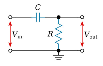
The first circuit we shall analyze is that of an RC high-pass filter, as shown in the figure above. Before launching into a mathematical analysis, we can deduce some of the electrical properties by visual inspection of the circuit.
If the applied voltage is of very high frequency, the reactance of C will be very low compared with R. Therefore, at high frequencies the input voltage Vin will appear virtually unattenuated at the output. Hence, we have the name high-pass filter. As the input frequency decreases, the reactance XC becomes larger, causing the input to be increasingly attenuated. At the zero frequency, XC will be infinitely high and therefore the output voltage Vout = 0.
To analyze the circuit mathematically, we would use the voltage-divider relationship and write

We shall, however, solve the ratio of Vout to Vin, since we generally wish to express the filter gain or loss. This ratio is called the transfer function. As a transfer function, we then have


where ωC = 1/RC is the characteristic frequency.
The transfer function can be expressed in polar form

Amplitude Characteristic
Consider first the amplitude characteristic (spectrum) corresponding to the equation above. This is the absolute value (magnitude) of the transfer function, or

On a decibel basis, this becomes


Let us examine the equation above for very low and for very high frequencies. For high frequencies, we have
![]()
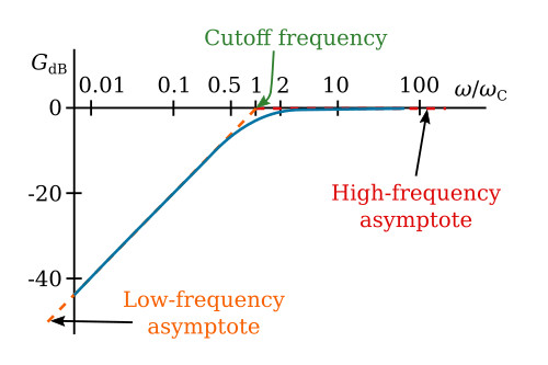
Thus, the high-frequency behavior is essentially independent of frequency and can be represented by a horizontal straight line at 0 dB as in the figure below. The actual amplitude characteristic given by the transfer function is asymptotic to this straight line for high ω.
For the other extreme, we have
![]()
This is of the form GdB = 20x, where x = log10 (ω/ωC). The straight line so defined is the low-frequency asymptote of the actual characteristic. The slope of the asymptote is dGdB/dx = 20; that is, when x increases one unit, GdB increases by 20 dB. But
![]()
and so ω/ωC must increase by a factor of 10, or one decade, to make x increase one unit. Therefore, the slope of the low-frequency asymptote is 20 dB per decade. Some people prefer to use the octave (frequency ratio of 2:1). The corresponding slope is 6 dB per octave. The two straight-line asymptotes intersect at ω/ωC = 1, for then the amplitude characteristic has the value zero. The two asymptotes are shown dashed in the figure above. Their point of intersection, ω = ωC, in addition to being termed the characteristic frequency of the circuit, is also called the break point, or cutoff frequency. Together, the two asymptotes form a broken-line approximation to the actual characteristic. Depending upon the accuracy desired, neither line may be a sufficiently good approximation to the actual characteristic in the neighborhood of ω = ωC. It can be shown that the maximum error occurs at ω/ωC = 1 and is approximately 3 dB. Further more, an octave away from this point (at ω/ωC = 0.5 and ω/ωC = 2) the error is approximately 1 dB. From this, it is easy to sketch the actual amplitude characteristic with reasonable accuracy. The actual characteristic is shown by the solid line in the figure above. The high-pass characteristic of the circuit is easily seen in this figure.
Phase Characteristic
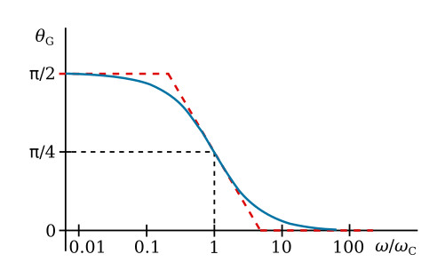
Let us now consider the angle of the transfer function of the filter (sometimes called the phase spectrum), which is
![]()
The phase angle starts at π/2 for ω = 0 and approaches 0 at large ω. The phase characteristic can be approximated reasonably well by three straight-line segments, as shown in the figure below: a low-frequency approximation at π/2 radians, a high-frequency approximation at 0 radians, and an intermediate-frequency approximation which is tangent to the curve at π/4 radians. The actual characteristic is shown by the solid line in the figure.