


Home > Textbooks > Basic Electronics > Filters > Quality Factor and Bandwidth >
Filters
Quality Factor and Bandwidth
Now we will discuss about a factor that, in effect, measures just how close to perfect a filter or filter component can be. This same factor affects bandwidth and selectivity. The factor is known as Q (quality factor). The higher the Q, the better the filter; the lower the losses, the closer the filter is to being perfect.
Although Q may be defined in several ways, a general definition that applies to any system is based on the ratio of the energy stored in the system to the energy dissipated per cycle:

This is the fundamental definition of Q, and all other definitions are derived from it. This equation applies to any type of resonant system including series-tuned and parallel-tuned circuits comprised of inductors and capacitors, transmission lines, microwave cavities, acoustic organ pipes, mechanical pendulums, and RC active circuits.
For an inductor or capacitor, Q turns out to be the ratio of the reactance to the resistance. For an inductor,

and for a capacitor,

where R in both instances is an equivalent series resistance. Applied to inductors and capacitors, Q is a measure of the quality of the component. The higher the Q, the more nearly does an inductor or capacitor approach the ideal component.
In a series-tuned circuit it is possible for the voltage across the inductor to be considerably greater than the voltage applied to the circuit. In fact, both the inductor and capacitor voltages will be nearly Q times the applied voltage, where Q is the quality factor of the overall circuit. Similarly, in a parallel-tuned circuit the circulating current will be nearly Q times the current entering the circuit.
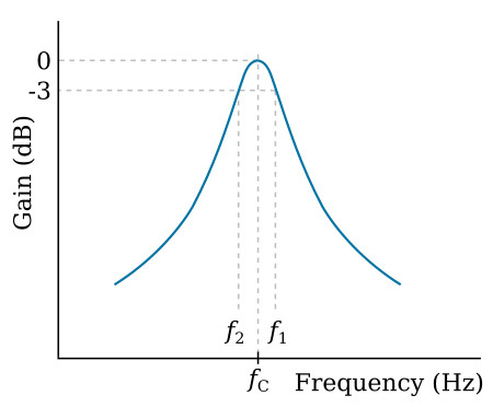
Q can be defined in a way that allows it to be used for tuned circuits as a measure of the selectivity or sharpness of tuning. The response curve for a tuned circuit is shown in the figure above, and the quality factor, Q, may be obtained as follows:

where fC is the center frequency of the tuned circuit, f1 is the upper 3-dB frequency, and f2 is the lower 3-dB frequency. Notice that since Q is a ratio of two frequencies, it is a dimensionless quantity, so that Q = ωC/(ω1-ω2) is also valid.
As explained below, f1 and f2 are often referred to as the half-power points: Let the power in a circuit having resistance R be P. If the voltage across the circuit is V,

If the power is halved, then

Thus the power is halved when the voltage is divided by √2. Expressing this in dB,

Accordingly, the half-power points occur at the frequency where the voltage is 3 dB down from the peak. It can also be shown that fC is the geometric mean of f1 and f2, that is,
![]()
Example:
A bandpass filter has a center frequency of 1000 Hz and a 3-dB bandwidth of
33.33 Hz. Find the circuit Q and the 3-dB frequencies.
Solution:

From the equation fC2 = f1f2
![]()
Also
![]()
Combining the previous two equations, and solving the resulting quadratic equation, there is obtained


