


Home > Textbooks > Basic Electronics > Filters > RC Active Filters >
Filters
RC Active Filters
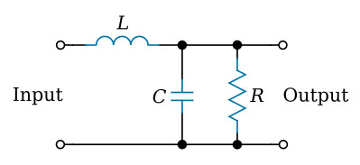
There are many ways in which filter circuits can be classified, for example, filters that use inductors and those that do not. The figure below shows a filter circuit consisting of an inductor L, a capacitor C, and a resistor R, but filters of this type may be formed without a resistor. The circuit is called an LC filter and is intended to pass a band of frequencies extending from DC to some cutoff frequency fC.
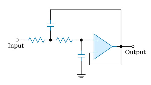
There are instances in which it is desirable to use a filter that does not require inductors; filter circuits without inductors present many advantages. The circuit for a low-pass filter that has an amplitude response identical to the LC filter in the figure above is shown in the figure below, and is seen to consist only of resistors, capacitors, and an active element in the form of an amplifier. The circuit is a characteristic example of an RC active filter. An active filter of this type includes more parts than a passive LC circuit and, in addition, requires a power supply; accordingly, the RC active circuit must have definite advantages if it is to take the place of an LC filter, but the most significant advantages result from the absence of an inductor. For low-frequency circuits, especially below 1 Hz, inductors are large and expensive. Large inductors also are not ideal because they have too much series resistance and stray capacitance. Inductors of over a few microhenries cannot be integrated either monolithically or in hybrid form; as a result, most LC filters cannot be miniaturized or mass-produced by modern microelectronic techniques. LC filters are troublesome even in discrete form because it is often difficult to obtain nonstandard values of inductances.
In contrast to passive LC filters, RC active filters can provide an impedance transformation; that is, they can have a high input impedance and a low output impedance, which means that network stages are isolated and can be tuned independently without interaction.
Many of the disadvantages of RC active filters result from the use of active elements, usually operational amplifiers. Amplifier outputs ordinarily have offsets that can range from a few microvolts to a few millivolts and have temperature coefficients of typically 1 to 100 microvolts per degree Celsius. Also, amplifiers usually have input bias currents that may flow through input circuit resistors and produce output voltage offsets; input bias currents also are a function of temperature. Moreover, the limited frequency response of operational amplifiers defines the high-frequency responses of RC active filters; ordinarily, the maximum bandwidth is usually about 100 kHz. In practice, the limiting factor is the slew rate of the operational amplifier. A high slew rate is necessary to prevent distortion of the output waveform at high frequencies when the output voltage is a few volts or more.
RC active filters are in widespread use because their advantages exceed their disadvantages in many applications. Many types of active filters are available as off-the-shelf components from a number of commercial sources, and one is advised to purchase filters whenever possible. However, there are many instances when it is necessary to design and build an RC active filter, and it is hoped this textbook will prove useful on such occasions.


