


Home > Textbooks > Basic Electronics > Filters > RC Active Low-Pass Filters >
Filters
RC Active Low-Pass Filters
This section describes the steps involved in the design of three types of low-pass filters: Butterworth, Chebyshev, and Bessel. First of all, it is necessary to select the appropriate filter for the application at hand; the types of filters were discussed previously and summarized in the table. The Butterworth is a general-purpose filter that provides good attenuation characteristics and maximum possible flatness in the pass region. The Chebyshev filter has a steeper attenuation slope in the region of cutoff, but this is achieved at the expense of ripple in the passband. The Bessel filter has a poor attenuation slope and also poor flatness in the passband. It is widely used for filtering pulses because its linear-phase characteristic minimizes the overshoot that can be a problem with low-pass Butterworth or Chebyshev filters.
After selecting one of the three basic types of filters, the next step is to decide on the number of poles that are to be used. For economy and simplicity, it is prudent to select a filter with the least possible number of poles. Elimination of unwanted signals and the reduction of noise are the two most common factors that govern the number of poles in the filter.
Example 1:
A unity-gain filter is required to pass all frequencies up to 1000 Hz with
maximum flatness. Signals of 4500 Hz and higher must be attenuated by at least
50 dB. How many poles are required in the filter?
Solution:
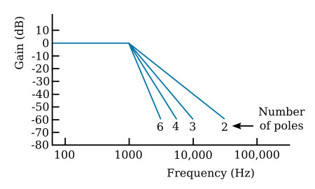
The figure below shows the idealized amplitude response curves for a Butterworth
filter (maximally-flat amplitude response) with 2, 3, 4, and 6 poles, the
number of poles for which designs are provided in this text. A 4-pole filter
will provide the necessary 50-dB attenuation for frequencies of 4500 Hz and above.
Example 2:
A unity-gain filter is required to pass all frequencies up to 200 Hz with
maximum flatness. Signals of 4000 Hz or more must be attenuated by 50 dB or
more. How many poles are required?
Solution:
The figure above applies to filters that have a cutoff at 1000 Hz. Because
frequency scaling does not affect the shape of the response curves, the data
in the figure may be applied to the problem of a 200-Hz cutoff filter by
dividing all numbers on the frequency scale by 5; the cutoffs are
thus converted to 200 Hz. Accordingly, the number of poles required to give
50 dB of attenuation at 4000 Hz is two (20,000 Hz divided by the scaling factor
is 4000 Hz).
The data given in the next three figures may be used to find out how much attenuation Butterworth, Chebyshev or Bessel low-pass filters with different numbers of poles will provide.
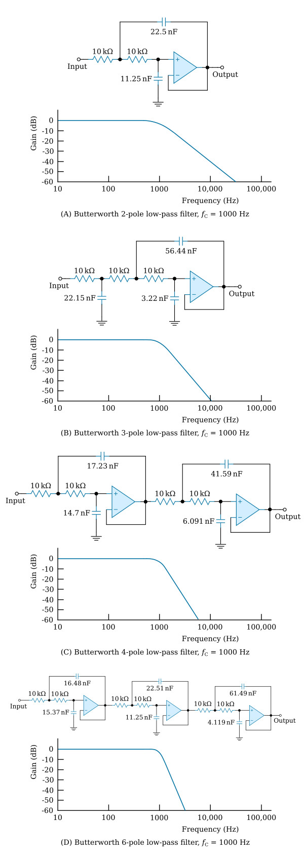
Butterworth Low-Pass Filters
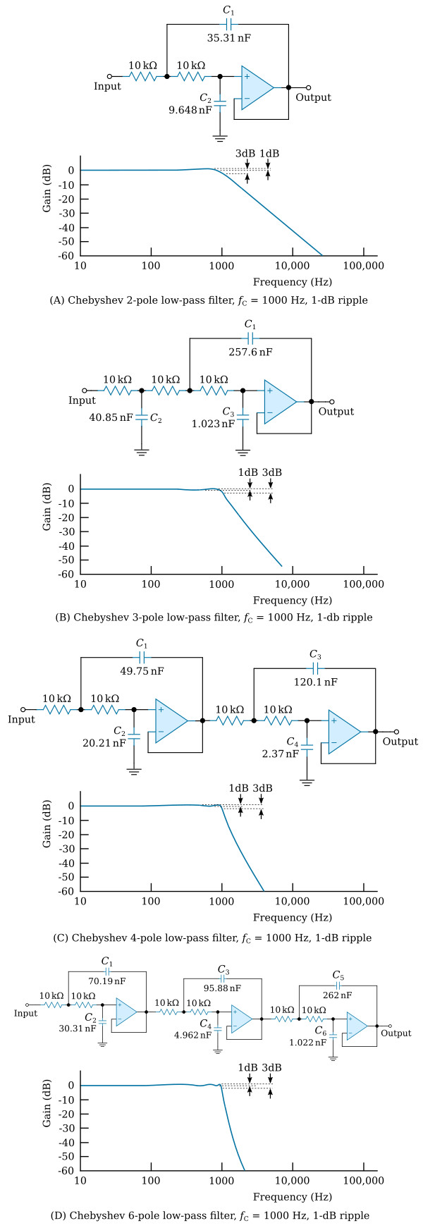
Chebyshev Low-Pass Filters
Bessel Low-Pass Filters

All the Butterworth and Bessel low-pass filters shown in the previous figures are 3 dB down at 1000 Hz. If the filters are scaled to another frequency by the techniques summarized in the previous table, the new cutoff frequency will also mark a 3-dB point.
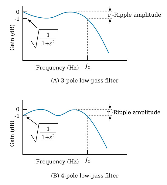
With Chebyshev filters, the situation is slightly more complicated, but it is easily resolved. Plots of the amplitude-responses of 3-pole and 4-pole 1-dB-ripple Chebyshev filters are presented in the figure above. The graphs in this figure are not drawn to scale in order to emphasize certain important features of the plots. The plots are values obtained from the classical formula for the amplitude response of the Chebyshev filters, which is

where ε is a constant that controls the degree of ripple height, and Cn(ω) is the Chebyshev polynomial, which is a function of the frequency and the number of poles. For a 3-pole Chebyshev, Cn(ω) = 4ω3-3ω, and for a 4-pole, Cn(ω) = 8ω4-8ω2 + 1.
The key features of interest at this time are the gains at DC and at the cutoff frequency fC; at cutoff, both filters are down by an amount equal to the ripple or -1 dB, which is to be contrasted with the fact that the cut off of many other filters is specified as occurring at -3 dB. Note that the 3-pole filter has a gain of 1 (0 dB) at DC, but that the 4-pole filter has a gain of -1 dB. In general, all 1-dB Chebyshev filters with an even number of poles will be down 1 dB at DC and at cutoff, while all those with an odd number of poles will be down 0 dB at DC and 1 dB at cutoff.
The Chebyshev filter circuits shown in this section differ in two ways from filters having the responses shown in the previous figure: (1) All low-pass filters in this section, including Chebyshevs, are designed to have a gain of unity (0 dB) at DC, whether they have an even or odd number of poles; (2) All cutoffs are specified as occuring at the -3 dB point; that is, -3 dB from the maximum gain. The maximum gain for filters with an odd number of poles occurs at DC and at certain other frequencies; for filters with an even number of poles, the maximum gain occurs at frequencies other than DC.
Selection of Values
Values for the components of low-pass filters that meet the requirements of a particular application are readily obtained by modifying an existing design with the frequency-scaling and impedance-scaling methods summarized in the previous table.
Design performance characteristics are given in the three figures shown above for 1000-Hz Butterworth, Chebyshev, and Bessel filters with 2, 3, 4, and 6 poles. If the application under consideration can be satisfied by a filter with a 1000-Hz cutoff, the required circuit is given, and no further design is necessary.
Example 3:
Design a 3-pole, low-pass Butterworth filter that has a 3-dB frequency of 1000 Hz.
Solution:
Since the required cutoff frequency is 1000 Hz, the design in the
figure of Butterworth 3-pole low-pass filter
can be used directly.
Example 4:
Design a 3-pole, low-pass Butterworth filter that has a 3-dB frequency of 1000 Hz.
The filter is to be used to condition signals from a circuit that has an output
resistance of 15,000 ohms.
Solution:
Since the cutoff frequency is 1000 Hz, the design in the
figure of Butterworth 3-pole low-pass filter
can be used directly; however, because the signal source acts as a 15,000 ohm
series resistance, it is necessary to use a buffer amplifier to provide the
low-impedance drive required by all the low-pass filters described in this section
of the textbook. If a buffer is not used, the 15,000-ohm source resistance will
sum with the 10,000-ohm input resistors of the filter and modify the response
to the extent that the filter is no longer a Butterworth and therefore will
not have the required 1000-Hz 3-dB frequency. A voltage follower, such as the
one shown in
this figure,
would make a suitable input buffer amplifier.
Example 5:
Design a 4-pole, low-pass Bessel filter with a 3-dB frequency of 200 Hz.
The circuit given in the figure above (view C) is a 4-pole, low-pass Bessel filter with a 3-dB frequency of 1000 Hz; accordingly, the circuit must be frequency-scaled to 200 Hz and the proper multiplying factor for all resistor values or all capacitor values is 1000/200 = 5 (see this table). All resistors in the modified circuit of the figure above (view C) should be 50,000 ohms; of course, the capacitor values remain unchanged.
In the new design, the series resistance seen by each amplifier has been increased from 20 kΩ to 100 kΩ; moreover, the output offset voltage will be increased because of unavoidable amplifier bias-current. For example, a 741-type operational amplifier has a bias current that is typically 200 nA; therefore, each amplifier would be offset by (200 nA) × (100 kΩ) = 20 mV and, since two amplifiers are involved, the total offset caused by the bias current of the operational amplifier would be typically (2) × (20 mV) = 40 mV. Some 741-type amplifiers have voltage offsets as much as 1 mV; if the voltage and current offsets happen to add, which would be a worst case, the total offset could be as high as 42 mV. This usually is an acceptable offset; if not, the 741 amplifiers can be replaced with FET amplifiers that ordinarily have much lower bias currents and comparable voltage offsets. Another possibility would be to maintain the resistor values given in the figure above (view C) and to increase all capacitor values by a factor of 5 (see this table).
Example 6:
Design a 6-pole Chebyshev low-pass filter with a cutoff of 10 Hz.
Solution:
The figure above (view D)
shows the circuit for a 6-pole Chebyshev low-pass filter that has a cutoff
of 1000 Hz.
The circuit in this figure can be frequency-scaled (see this table), and either the resistor values or the capacitor values can be scaled. Suppose it is decided to increase the resistor values by the multiplying factor (1000 Hz)/(10 Hz) = 100; all resistors for the new circuit will have the value of one megohm. If 741-type operational amplifiers with 200-nA bias currents are used, the offset per section will be (200nA) × (2MΩ) = 0.4 V. Since there are three sections in the filter, the total offset attributable to bias currents could be as much as (3) × (0.4 V) = 1.2 V. If the offset is unacceptably high, it can be reduced by using an FET amplifier.


