


Home > Textbooks > Basic Electronics > Filters > RC Active High-Pass Filters >
Filters
RC Active High-Pass Filters
This section describes the steps involved in the design of Butterworth, Chebyshev, and Bessel high-pass filters; the first step is to select the type of filter that is most appropriate for the application in mind, and for this purpose it is well to review the general characteristics of each type as presented previously and summarized in the table. For example, it has been explained that the Butterworth is an excellent general purpose filter with good attenuation characteristics and the maximum possible flatness in the passband. In contrast, the Chebyshev has a steeper attenuation-slope in the region of cutoff, but this is achieved at the expense of having ripple in the passband. Bessel filters have poor attenuation-slope and poor flatness in the pass region; also, they are not very useful as high-pass filters because their linear phase properties are lost when low-frequency circuits are scaled to higher frequencies.
Having selected one of the three basic types of filters, the next step is to decide on the number of poles required. For reasons of economy and simplicity, one usually selects a filter with the least number of poles that will do the job. Usually, elimination of unwanted signals and reduction of noise are the pivotal factors in the selection of the number of poles.
Example 1:
A unity-gain filter is required to attenuate all frequencies
up to 1000 Hz; maximum flatness in the passband is required and signals
of 60 Hz and less must be attenuated by at least 60 dB. How many poles
are required in the filter?
Solution:
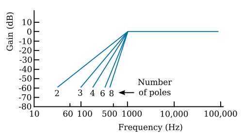
The idealized amplitude-response curves for Butterworth
(maximally-flat amplitude response) filters with 2, 3, 4, and 6 poles are
shown in the figure below. Inspection of this figure reveals that a 3-pole
filter will provide the necessary 60-dB attenuation for frequencies of 60 Hz
and below.
Example 2:
A unity-gain filter is required to attenuate all frequencies
below 2000 Hz; maximum flatness in the passband is required and signals of
1000 Hz and below must be attenuated by at least 45 dB. How many poles
are required?
Solution:
Data given in the figure above are for filters with 1000-Hz cut-offs,
but it is to be recalled that frequency-scaling does not affect the shape of
response curves. Consequently, the data in the figure can be applied to the
problem of a 2000-Hz filter by multiplying all values on the frequency scale
by 2 (to provide a cutoff of 2000 Hz). Continuing, the number of poles
required to give 45 dB of attenuation at 1000 Hz is 8, because 500 Hz
multiplied by 2 is 1000 Hz.
The data given in the next three figures may be used to find out how much attenuation Butterworth, Chebyshev or Bessel high-pass filters with different numbers of poles will provide.
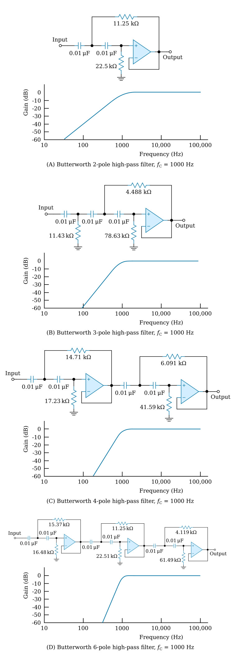
Butterworth High-Pass Filters
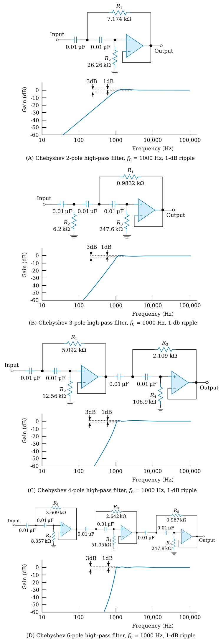
Chebyshev High-Pass Filters
Bessel High-Pass Filters

Selection of Values
Values for high-pass filters are readily obtained by modifying an existing design by frequency-scaling and impedance-scaling (see this table) to meet the requirements for a particular application.
Designs for high-pass Butterworth, Chebyshev, and Bessel filters that have 2, 3, 4, and 6 poles and a 1000-Hz cutoff are given in the previous three figures. If an application can use a filter with a cutoff of 1000 Hz, the circuit can be taken from the appropriate figure; no design changes are necessary.
Example 3:
Design a 3-pole, high-pass Butterworth filter with a 3-dB frequency of 1000 Hz.
Solution:
Since the cutoff frequency is 1000 Hz, the design in the
figure of Butterworth 3-pole high-pass filter
can be used directly with no modification.
Example 4:
Design a 3-pole, high-pass Butterworth filter with a 3-dB
frequency of 1000 Hz. The filter is to be used to filter signals from a circuit
that includes a 0.02-μF series-output capacitor.
Solution:
Since the cutoff frequency is 1000 Hz, the design of the
figure of Butterworth 3-pole high-pass filter
can be used; however, because there is a 0.02-μF capacitor in the output
of the signal source, a buffer amplifier is necessary to provide the low-impedance
drive required by all the high-pass filters described in this section of the
textbook. If a buffer is not used, the 0.02-μF capacitor will modify the
filter RC network to the extent that it no longer is a Butterworth and thus
will not have a 1000-Hz, 3-dB cutoff frequency. A voltage follower such as
the one shown in
this figure
would make a suitable buffer, but a resistor must be connected from the + input
to ground to provide a continuous DC path. The
resistor, R, and the 0.02-μF source capacitor C, will of
themselves form a high-pass filter. The effect of this filter on the overall
circuit performance can be rendered negligible by selecting a value for R
of such magnitude that at 1000 Hz the RC network will have negligible attenuation.
Example 5:
Design a 4-pole, high-pass Bessel filter with a 3-dB frequency of 2000 Hz.
Solution:
The circuit shown in the figure above (view C)
is for a 4-pole, high-pass Bessel filter that has a 3-dB frequency of 1000 Hz.
The solution is, therefore, to frequency-scale this circuit to 2000 Hz. From
this table,
all resistor values or all capacitor values can be multiplied by 1000/2000 or
0.5. It is probably most convenient to change all capacitors from 0.01 to 0.005 μF.
Example 6:
Design a 6-pole Chebyshev high-pass filter with a cutoff at 1 Hz.
Solution:
The figure above (view D)
shows the circuit for a 6-pole Chebyshev high-pass filter with cutoff at 1000 Hz.
This circuit can be frequency-scaled
(see this table)
and either the resistors or the capacitors can be changed; for example, increase
all the capacitors to 10 μF by
using a multiplying factor of 1000. The circuit is now frequency-scaled to
1 Hz, but 10 μF is an inconveniently large value; since 1 μF
would be better, all capacitors should be further multiplied by 0.1 and all
resistors by 10. The filter is still frequency-scaled to 1 Hz, but
has been impedance-scaled to more convenient values. Note that the resistor
on the last operational amplifier in
the figure above (view D)
is 247.8 kΩ, but this has been impedance-scaled to 2.477 MΩ. Since
this resistor serves as the bias resistor for the operational amplifier, an FET
type of amplifier should be used to minimize offsets resulting from input bias currents.
When high-pass Chebyshev filters with greater or less ripple than the 1-dB value used thus far are required, it is necessary to adopt the resistance values given in the table below (for filters with 0.25-dB and 3-dB of ripple). For example, to convert the 1-dB ripple of the filter shown in the figure above (view A) to a filter of 0.25-dB ripple, R1 and R2 should be changed to 8.946 kΩ and 23.44 kΩ, respectively. The capacitor values remain unchanged.
| 0.25 dB ripple | ||||
|---|---|---|---|---|
| Number of poles | 2 | 3 | 4 | 6 |
| R1 | 8.946 | 1.861 | 7.164 | 5.227 |
| R2 | 23.44 | 7.885 | 12.38 | 8.484 |
| R3 | 143.5 | 2.968 | 3.826 | |
| R4 | 76.35 | 37.04 | ||
| R5 | 1.4 | |||
| R6 | 170.7 | |||
| 3 dB ripple | ||||
| Number of poles | 2 | 3 | 4 | 6 |
| R1 | 5.129 | 0.3665 | 3.272 | 2.271 |
| R2 | 34.92 | 4.385 | 15.17 | 9.906 |
| R3 | 628.2 | 1.355 | 1.662 | |
| R4 | 168.7 | 79.51 | ||
| R5 | 0.6084 | |||
| R6 | 397.5 | |||
Resistance values for 0.25-dB and 3-dB ripple Chebyshev high-pass filters with 1000-Hz cutoffs. C = 0.01 microfarad, resistance values are in thousands of ohms.


