Home > Textbooks > Basic Electronics > Wave Shaping > Precision Limiter >
Wave Shaping
Precision Limiter
The precision limiter frequently used in the analog preprocessing circuitry is shown in the figure below. In this circuit, the high open-loop gain of the operational amplifier (op-amp) is used to reduce the effect of the diode nonlinearity and the temperature sensitivity. Using the usual op-amp relationships, the circuit can be analyzed.
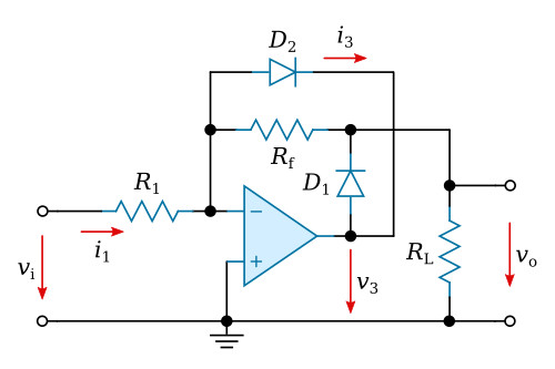
For v3 > 0 (vi < 0), the current i3 will be zero because D2 is reverse-biased. If the infinite amplifier gain is considered, all input current i1 flows through Rf to D1 (forward-biased) and RL, generating an output voltage

The effect of the diode forward voltage vD1 is reduced by the loop gain of the closed-loop circuit. The "rounding" of the turn-on region therefore virtually disappears.
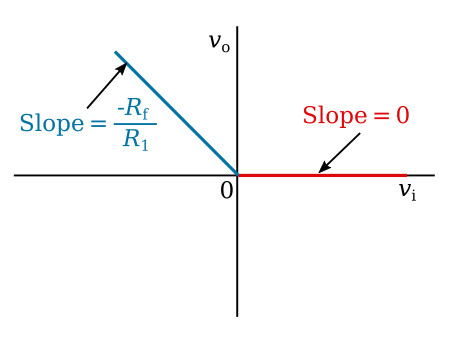
For v3 < 0, diode D1 no longer conducts and all the input current i1 flows through D2. Theoretically, the output voltage is then exactly equal to zero. Thus, the precision limiter provides a good approximation of ideal diode behavior, reducing the diode nonlinearity, temperature sensitivity, and forward voltage drop by a factor equal to the loop gain of the amplifier. The transfer curve for the precision limiter is given in the figure below.