Home > Textbooks > Basic Electronics > Logic Gates > AND Gate >
Logic Gates
AND Gate
The AND gate is a logic circuit that requires all inputs to be TRUE at the same time in order for the output to be TRUE.
Logic Symbol
The standard symbol for the AND gate is shown in the figure below. Variations of this standard symbol may be encountered. These variations become necessary to illustrate that an AND gate may have more than two inputs.
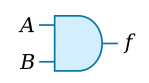
If we apply two variables, A and B, to the inputs of the AND gate, then both A and B would have to be TRUE at the same time to produce the desired TRUE output. The symbol f designates the output function. The Boolean expression for this operation is f = A · B or f = AB. The expression is spoken, "f = A AND B." The dot, or lack of, indicates the AND function.
AND Gate Operation
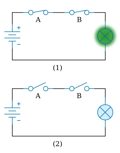
We can demonstrate the operation of the AND gate with a simple circuit that has two switches in series as shown in the figure below. You can see that both switches would have to be closed at the same time to light the lamp (view 1). Any other combination of switch positions (view 2) would result in an open circuit and the lamp would not light (logic 0).
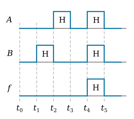
Now look at the figure below. Signal A is applied to one input of the AND gate and signal B to the other. At time t0, both inputs are LOW (logic 0) and f is LOW. At t1, B goes HIGH (logic 1); A remains LOW; and as a result, f remains LOW. At t2, B goes LOW and A goes HIGH; f, however, is still LOW, because the proper input conditions have not been satisfied (A and B both HIGH at the same time). At t4, both A and B are HIGH. As a result, f is HIGH. The input requirements have been satisfied, so the output is HIGH (logic 1).
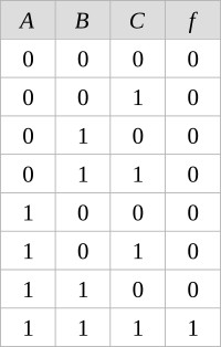
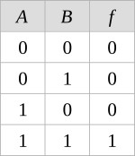
Truth Table
Now let’s refer to the figure below, where a Truth Table is shown. As we mentioned earlier, the Truth Table is a chart that shows all possible combinations of inputs and the resulting outputs. Compare the AND gate Truth Table (figure below) with the input signals shown in the figure above. The first combination (A = 0, B = 0) corresponds to t0 in the figure above; the second to t1; the third to t2; and the last to t4. When constructing a Truth Table, you must include all possible combinations of the inputs, including the all 0s combination.
A Truth Table representing an AND gate with three inputs (A, B, and C) is shown below. Remember that the two-input AND gate has four possible combinations, with only one of those combinations providing a HIGH output. An AND gate with three inputs has eight possible combinations, again with only one combination providing a HIGH output. Make sure you include all possible combinations. To check if you have all combinations, raise 2 to the power equal to the number of input variables. This will give you the total number of possible combinations. For example:
Example 1: AB -> 22 = 4 combinations
Example 2: ABC -> 23 = 8 combinations