


Home > Textbooks > Basic Electronics > Logic Gates > Diode-Transistor Logic (DTL) >
Logic Gates
Diode-Transistor Logic (DTL)
Diode-transistor logic (DTL) was one of the most popular manufactured circuits. The basic DTL circuit is a diode AND with a transistor inverter. The figure below shows the basic DTL configuration which is a NAND circuit.
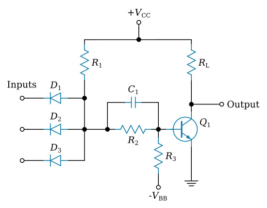
The divider network, consisting of R1, R2, and R3, is designed such that if all the input voltages are HIGH (logic 1), the base of Q1 is relatively positive and Q1 is on. The output voltage at the collector of Q1 is almost zero. If any of the inputs now swing to 0 volt, that particular diode conducts. This applies a relatively negative voltage to the base of the transistor which is now cutoff. The collector tends to rise to the supply voltage +VCC. Capacitor C1 is used to provide an overdrive current during switching time. This reduces the switching time to some extent.


