Home > Textbooks > Basic Electronics > Logic Gates > NAND Gate >
Logic Gates
NAND Gate
The NAND gate is another logic device commonly found in digital equipment. This gate is simply an AND gate with an inverter (NOT gate) at the output. The logic symbol for the NAND gate is shown in the figure below.

The NAND gate can have two or more inputs. The output will be LOW only when all the inputs are HIGH. Conversely, the output will be HIGH when any or all of the inputs are LOW.
The NAND gate performs two functions, AND and NOT. Separating the NAND symbol to show these two functions would reveal the equivalent circuits depicted in the figure below. This should help you better understand how the NAND gate functions.

Signals A and B are applied to the AND gate. If either A or B or both are LOW, then the output of the AND gate is LOW. A LOW on the input of the inverter results in a HIGH output. When both A and B are HIGH, the output of the AND gate is HIGH; thus the output of the inverter is LOW. The Boolean expression for the output of a NAND gate with these inputs is f = AB.
NAND Gate Operation
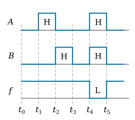
Now, let’s observe the logic level inputs and corresponding outputs as shown in the figure below. At time t0, A and B are both LOW. The output is HIGH; the opposite of an AND gate with the same inputs. At t1, A goes HIGH and B remains LOW. As a result, the output remains HIGH. At t2, A goes LOW and B goes HIGH. Again, the output remains HIGH. When both A and B are HIGH at t4, the output goes LOW. The output will remain LOW only as long as both A and B are HIGH.

Truth Table
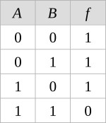
The Truth Table for a NAND gate with A and B as inputs is shown below.


