


Home > Textbooks > Basic Electronics > Logic Gates > CMOS Logic >
Logic Gates
CMOS Logic
Complementary metal oxide semiconductor (CMOS) technology employs both P-channel and N-channel MOS transistors on the same silicon substrate. Both types are enhancement-mode devices; that is, gate voltage must be increased in the direction that inverts the surface in order for the device to conduct. An enhancement-mode device is normally turned off. The N-channel and P-channel devices are connected in series. Only one device is turned on at a time, resulting in extremely low power dissipation. Dissipation is primarily from the switching of devices through the active region and the charging and discharging capacitances.
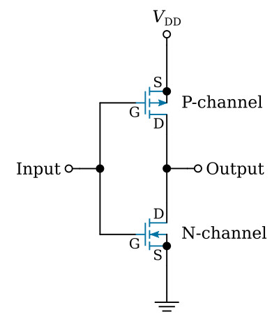
A typical CMOS inverter circuit is shown in the figure below. With the input at zero volts or ground, the upper P-channel MOSFET is properly biased and, therefore, conducts. The lower N-channel device is cut off at this time. The output is about the same as the supply voltage VDD. When the input voltage is a positive value approaching the supply voltage, the upper P-channel device cuts off. The lower N-channel device conducts and the output approaches zero volts. This basic circuit can be modified by adding additional P-channel and N-channel devices to form a variety of logic gates and storage elements.
The RCA 4000 series and 74HC series are popular CMOS logic families. The 4000 series is specified for a supply voltage range of 3 V to 18 V. The 74HC series allows operation from 2 V to 6 V. Their high noise immunity and low power consumption make them ideal for many industrial applications.


