Home > Textbooks > Basic Electronics > Logic Gates > NOR Gate >
Logic Gates
NOR Gate
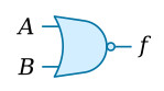
The NOR gate is an OR gate with an inverter on the output. The NOR gate will have a HIGH output only when all the inputs are LOW. The standard logic symbol for this gate is shown in the figure below. More than just the two inputs may be shown.
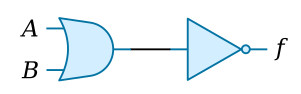
When broken down, the two functions performed by the NOR gate can be represented by the equivalent circuit depicted in the figure below. When both inputs to the OR gate are LOW, the output is LOW. A LOW applied to an inverter gives a HIGH output. If either or both of the inputs to the OR gate are HIGH, the output will be HIGH. When this HIGH output is applied to the inverter, the resulting output is LOW. The Boolean expression for the output of this NOR gate is f = A + B.
NOR Gate Operation
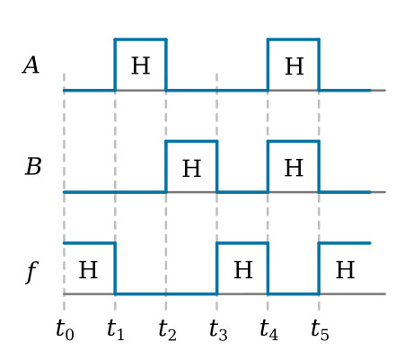
The logic level inputs and corresponding outputs for a NOR gate are shown in the figure below. At time t0, both A and B are LOW; as a result, f is HIGH. At t1, A goes HIGH, B remains LOW, and f goes LOW. At t2, A goes LOW, B goes HIGH, and the output remains LOW. The output goes HIGH again at t3 when both inputs are LOW. At t4 when both inputs are HIGH, the output goes LOW and remains LOW until t5 when both inputs go LOW. Remember the output is just opposite of what it would be for an OR gate.
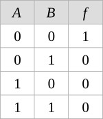
Truth Table
The Truth Table for a NOR gate with A and B as inputs is shown below.